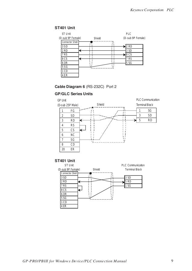
Keyence Wiring Diagram
Safety Light Curtain Simple Installation Keyence America

Mo 5599 Keyence Wiring Diagram Schematic Wiring

Keyence Fs V22 Series Sensor Manual Manualzz
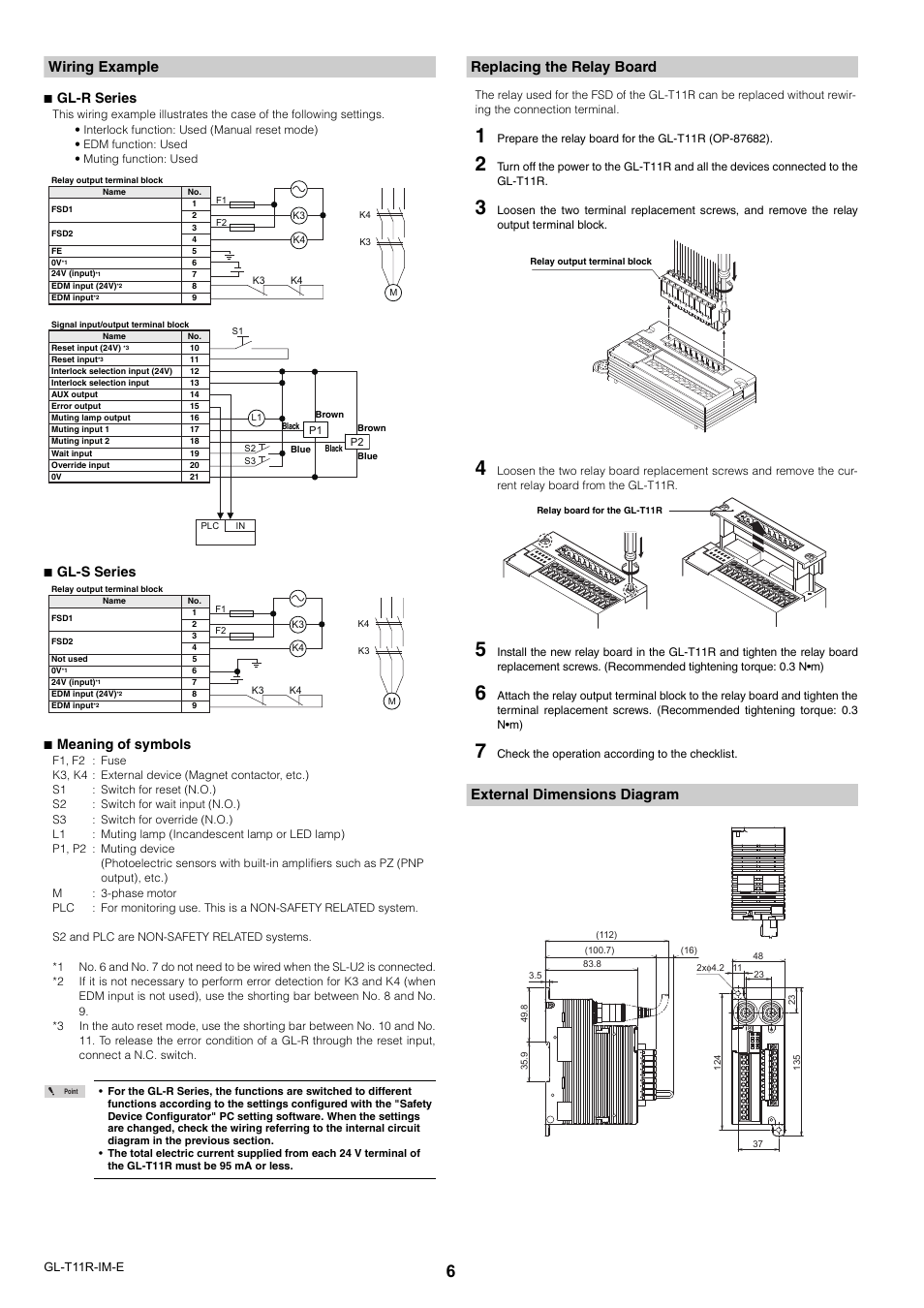
Wiring Example Replacing The Relay Board External Dimensions Diagram Keyence Gl T11r User Manual Page 6 8
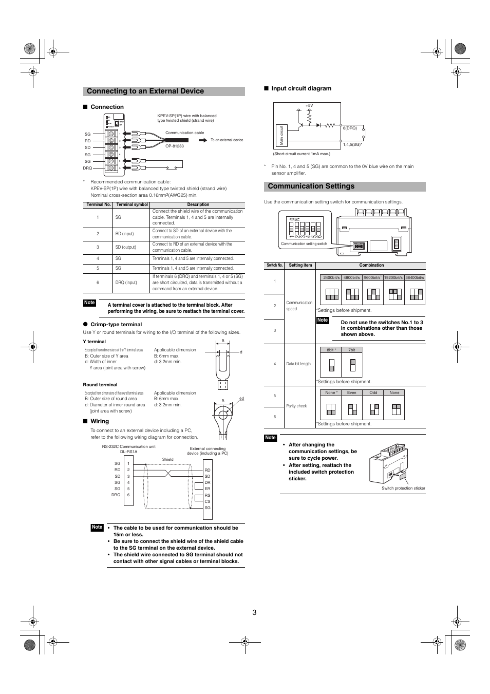
Connecting To An External Device Connection Wiring Keyence Dl Rs1a User Manual Page 3 4 Original Mode

Wiring Internal Circuit Diagram Gl R Series Keyence Gl T11r User Manual Page 5 8

Pnp npn totem pole output 2 outputs.
Keyence wiring diagram. It shows the components of the circuit as simplified shapes and the power and signal contacts amid the devices. 10 ma for edm non safety related output aux output output type. Input safety related input resistance. Gl t11r safety relay terminal in gl r series by keyence america.
Open or 10 v to power voltage short circuit current. Page 2 introduction this manual describes the basic operations and hardware functions of the fs n10 series. Open or 0 to 3 v short circuit current. Open or 0 to 3 v short circuit current.
4 4 kω for input 1 2 2 kω for input 2 non safety related output aux output output. 10 ma for edm non safety related output aux output output type. Keep this manual in a safe place for future reference. 0 to 3 v off voltage.
Mm sensor amplifier din rail mount type ig 1000 ig 1050 ig 1050 ig 1000 cable diameter ø4 7 cable diameter ø4 8 cable diameter ø4 7 cable length 2 m cable length 2 m 28 3 28 3 18 5 18 5 18 5 18 5 4 8 cable diameter ø4 8 19 2 69 5 max 135. 0 to 3 v off voltage. We have 1 keyence lv s41 manual available for free pdf download. 10 ma for edm npn.
10 to 30 v off voltage. 2 5 v with a cable length of 5 m 16 4 muting lamp output. Page 1 96141e digital fiber sensor fs n10 series user s manual read this manual before use. 10 ma for edm npn.
Read the manual carefully to ensure safe performance and function of the fs n10 series. When performing electrical wiring always fulfill the electrical standards and regulations for the country or region in which the sz is used. User manual keyence lv s41 user manual 112 pages. Keyence does not guarantee the function or performance of the sz if it is used in a manner that differs.
Residual voltage during on max. Keyence sr 1000 wiring diagram wiring diagram is a simplified tolerable pictorial representation of an electrical circuit. Keyence corporation of america 500 park boulevard suite 200 itasca il 60143 u s a. 10 to 30 v off voltage.
Wiring diagram dimensions unit.
Keyence Gv Series User Manual 10 Pages
Keyence Wiring Diagram All Wiring Diagrams
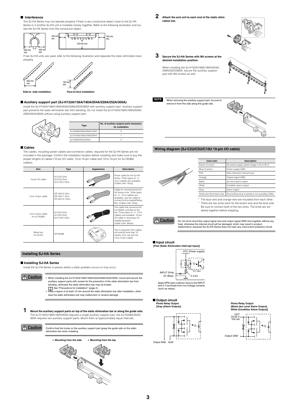
Installing Sj Ha Series Wiring Diagram Sj C2u C5u C10u 10 Pin I O Cable Caution Keyence Sj Ha Series User Manual Page 3 12 Original Mode
Http Static6 Arrow Com Aropdfconversion D5bb5bc5bd2f390f54708fef1b03af99b4f897dc Il 1500 Us En Us Pdf

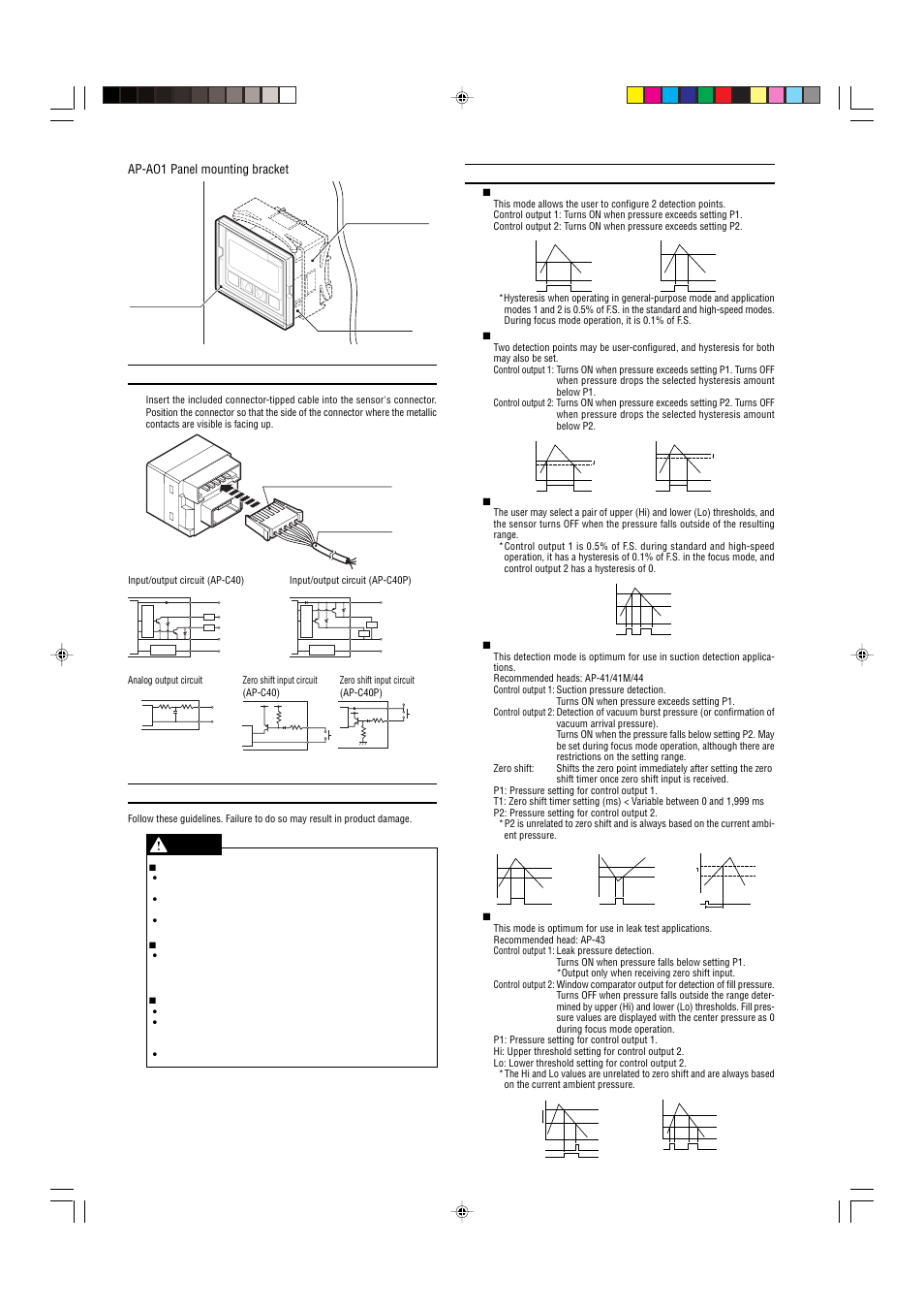
Keyence Ap C30kp User Manual 5 Pages

Keyence Wiring Diagram H1 Wiring Diagram

Keyence Lr Zb250an Ap User Manual 4 Pages

Error Displays And Corrective Actions Troubleshooting I O Circuit Diagram Keyence Gv Series User Manual Page 9 10

Installing Sj H Series Wiring Diagram Sj C2u C5u C10u 10 Pin I O Cable Caution Keyence Sj H Series User Manual Page 3 14 Original Mode
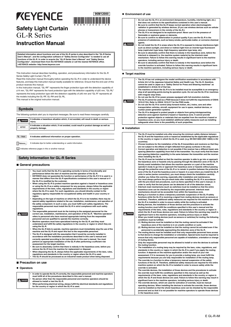
Keyence Gl R Series User Manual 12 Pages

2 Connecting And Mounting The Sensor Head Mounting The Sensor Head 2 Connecting And Mounting The Sensor Head 8 Keyence Il Series User Manual Page 28 140
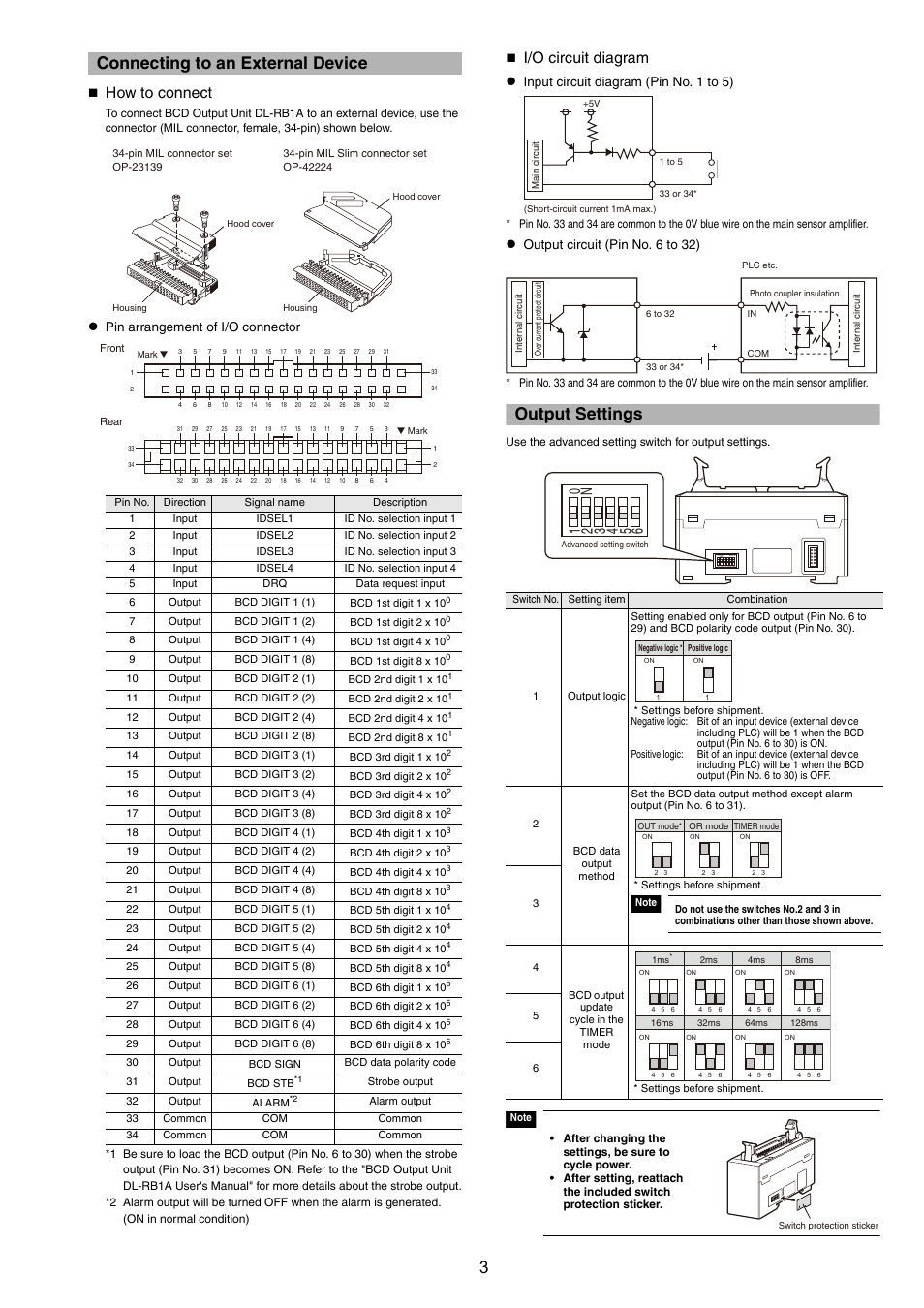
Connecting To An External Device How To Connect I O Circuit Diagram Keyence Dl Rb1a User Manual Page 3 4 Original Mode